
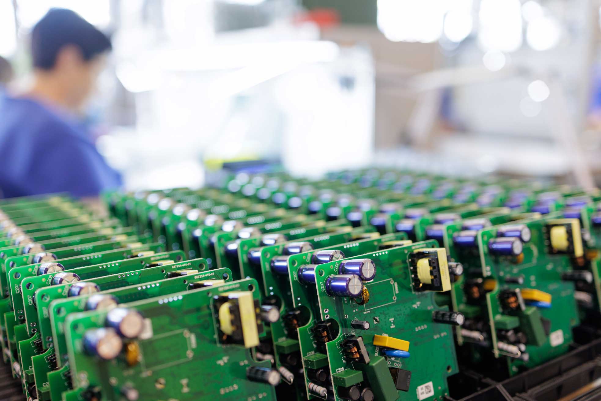
Design-for-Manufacturing exists because PCB respins are expensive, but largely avoidable. A 2018 Lifecycle Insights study found projects averaging 2.9 respins at roughly $44,000 each, a cost that compounds in schedule slip as much as in dollars.
DFM is the discipline that prevents them: aligning the board layout with what fabrication and assembly can actually do, so the board builds reliably, at yield, at the lowest practical cost.
This guide covers what DFM means for PCBs, the IPC standards behind it, the layout rules and errors to check before release, what’s changing in 2026, and the decisions that drive cost.
What Is Design-for-Manufacturing in PCB Design?
Design-for-Manufacturing (DFM), also called design for manufacturability, is the practice of designing a circuit board so it is easy, consistent, and economical to fabricate and assemble. That means tailoring the layout to the real capabilities, tolerances, and limits of the fab rather than the idealized geometry in your EDA tool.
In PCB work, that touches nearly everything: layout, component selection, via design, pad geometry, thermal management, solderability, even silkscreen legibility. It’s often framed as the union of Design for Fabrication (DFF), which concerns the bare board, and Design for Assembly (DFA), which concerns populating it.
The economics follow the 1-10-100 “Rule of Ten”: as an order-of-magnitude heuristic, a defect costs roughly ten times more to fix at each stage it survives. The cheapest place to catch a manufacturability problem is in layout.
Terms to Know: DFM vs. DFA, DFMA, DFx — and Why DFM Isn’t DRC
Start with the distinction that trips up the most designers: a design rule check (DRC) validates a layout against predefined rules inside the EDA tool, while DFM validates it against a real fabricator’s process capabilities and simulates actual manufacturing and assembly. Passing DRC does not mean a board will be built without problems.
The related acronyms sort out cleanly:
- DFM — producible and economical: process, materials, geometry, tolerances.
- DFA — easy to assemble: fewer parts, consistent orientation, self-locating features.
- DFMA — the combined DFM + DFA methodology.
- DFx (Design for Excellence) — the umbrella term, where “x” can be test, reliability, cost, or sustainability.
One misconception worth retiring: DFM is not solely the fab’s job. It’s a responsibility shared between designer and manufacturer.
Understanding The Standards Backbone of Design-for-Manufacturing: IPC-2221C, Classes, and Trace Widths
IPC-2221 is the generic standard on printed board design and the foundation of the IPC-2220 series. The current revision, IPC-2221C, was published in December 2023, superseding IPC-2221B (2012). Revision C expands coverage of material and copper-foil selection, panelization, edge-board plating, minimum electrical clearance (including creepage and corona effects), impedance tolerances, back-drilling, and press-fit pins, and adds altitude and vacuum spacing categories aligned with IEC 62368-1.
Around it sit the companions: IPC-6012 for rigid-board performance and acceptance, IPC-A-600 for visual acceptability, IPC-7351 for footprints, and IPC-2152 for current-carrying capacity. This standard supersedes IPC-2221’s legacy 1950s-era trace-width charts, which many online calculators still quote.
IPC also defines three product classes:
- Class 1 (general electronics),
- Class 2 (dedicated service),
- Class 3 (high reliability).
Class drives annular-ring minimums and acceptance criteria, so choose deliberately. Over-specifying Class 3 when Class 2 suffices raises cost for no benefit, but under-specifying risks field failures.
Common DFM Errors (and the Rules That Prevent Them)
These are the issues fabricators flag most often, each with the rule that prevents it:
Insufficient Annular Ring
The copper around a drilled hole; too little, and drill wander causes breakout and opens. Hold minimums per IPC Class requirements — as a rule of thumb, more than 3.5 mil per side on vias and 6 mil on through-hole pins — and verify against your fab’s capability sheet.
Trace Width and Spacing at the Limit
HDI work commonly runs 3-mil trace / 4-mil space, but fab tolerance is typically ±10–20%. Design to a published capability: Imagineering, for example, holds 0.003″/0.003″ at 0.5 oz copper and 0.004″/0.004″ at 1 oz.
Excessive Aspect Ratio
Board thickness divided by drill diameter; keep it at or below 10:1 for reliable hole plating.
Acid Traps
Acute angles under 90° trap etchant and over-etch traces. Route at 45° or 90°.
Tombstoning
Small passives (0402, 0201) lift on one end during reflow when pad wetting is unequal. Use symmetrical pads, matched trace widths, and consistent orientation, and note that HASL increases tombstoning roughly 3–5× versus ENIG.
Slivers and Solder-Mask Issues
Enforce minimum feature widths, keep mask dams at 4 mil or wider, and add teardrops where traces meet pads.
Panelization Clearances
Keep copper at least 3 mm (⅛″) from cut lines, whether you V-score or use mouse bites.
The meta-rule: run DFM iteratively . Shoot for 10 to 20 checks per design stage, not just once at the end when fixes are most expensive.
What’s Changed: DFM in 2026
Three shifts are reshaping the discipline of design-for-manufacturing.
1. Miniaturization
HDI boards now reach via diameters near 75 µm with 50 µm line widths, and ultra-HDI pushes below 2-mil lines. At these geometries, the margin for manufacturability error effectively disappears.
2. AI-Assisted Design
Cadence, Siemens, and Altium are integrating machine learning into placement and routing, while AI-native tools simulate manufacturing to catch issues ( tombstoning, clearance violations) that DRC never sees.
3. Intelligent Data Formats
The industry is moving from bare Gerber toward ODB++ and IPC-2581, which carry stackup, netlist, BOM, and DFM intent in a single file and enable bidirectional feedback with the fab. With Fortune Business Insights valuing the PCB market at $74.12 billion in 2025 — growth driven by AI, EVs, and 5G — features will only get finer, and early DFM more critical.
Decision Factors: Surface Finish, Copper Weight, File Format
The HASL-versus-ENIG choice usually comes down to the BOM. HASL is the cheapest, most durable finish but is too uneven for fine-pitch parts. ENIG’s flat, coplanar surface suits BGAs and QFNs at roughly $0.20–0.30 more per square inch. Any BGA, QFN, or ≤0.5 mm-pitch component triggers ENIG.
Beyond finish, copper weight sets the trace width your current demands, layer count and board size lock in most of the cost before routing begins, and you should send the most intelligent file format your fab supports.
Build Confidence in your Design-For-Manufacturing Process with Imagineering
DFM is not a final gate in the PCB fabrication process. It is a shared discipline that starts before the layout hardens. The throughline is simple: design around real fabrication capabilities, follow current standards like IPC-2221C and IPC-2152, check the errors that cause most respins, and plan for finer HDI geometries, smarter data formats, and tighter tolerances.
The best next step is also the most practical: bring your fabricator into the conversation early. Imagineering publishes clear fabrication tolerances and works with customers to identify manufacturability risks before they become production delays. Work with Imagineering to turn your PCB design into a board that is built for fabrication, not just ready for release.
Quick Summary
Understanding the PCB fabrication process helps engineers, buyers, and hobbyists see how a circuit board moves from design files to a finished, assembly-ready product. This blog walks through the major stages of PCB fabrication, including file review, material and stackup selection, imaging, etching, drilling, plating, finishing, and testing. It also explains how working with an experienced PCB manufacturer like Imagineering can help improve manufacturability, quality, and production readiness.
PCB Fabrication Process FAQs
The PCB fabrication process is the series of steps used to turn design files into finished bare printed circuit boards. It typically includes design review, material selection, imaging, etching, lamination, drilling, plating, finishing, and testing.
Most PCB fabrication projects require Gerber X2, ODB++, or IPC-2581 files, along with drill files, stackup details, drawings, and production notes. A complete manufacturing package helps the fabricator review the design accurately before production begins.
PCB fabrication creates the bare printed circuit board itself. PCB assembly comes afterward, when electronic components are placed and soldered onto the fabricated board.