The world becomes a more technologically advanced place every day; there is no denying that. By and large, people forget that there are still components that have to be made to make the technological devices we love so much work.
All the types of circuit boards that make up all the world’s toys from the iPhone to the PlayStation would not exist without PCBs. That’s why these boards remain in such high demand.
But what are they? What makes each one different? Is there a difference? Plenty! Learn all these things and more in this guide we have presented for you today.
The Many Types of Printed Circuit Boards
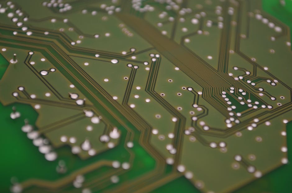
A printed circuit board or PCB is a physically supporting board while connecting electrically various electronic components of a more extensive system. The board uses conductive tracking, padding, and other items echoed from layers of copper.
Single-Sided
As the name suggests, the single-sided PCB is made from one material as a base, also known as a “substrate.” On top of that base is a thin foil layer made of copper. This is used as a conductor for the electric signal.
These are the most common of the PCB types and are very popular in large volume production because of their low price point. These boards are often found in cameras, calculators, and radio devices.
They can also be found in simple toy design.
Double-Sided
The double-sided PCB works in a manner very similar to the single, but both sides are sandwiched between the conductive layer. In addition to this, they are designed with holes drilled into the board itself.
These holes are placed into the board to allow the circuitry to be mounted on either side of the PCB or to be fed through the board. The extra flexibility and conductive surfaces place the double-sided in more advanced applications.
Double-sided PCBs can regularly be found in cell phones, vending machines, automobile displays, and electric metering equipment.
Multi-Layer
This design takes the double-sided and continues to expand on it. The multi-layer is a collection of no fewer than three (3) double-sided PCBs. They take the technology established here and enhance the production power of it.
The size and space are the main benefits of a multi-layer PCB. They can replace the need for several boards with a single multi-layer.
They are an integral part of high-speed circuitry as their board size allows for proper conductor layout and power.
Rigid
A rigid PCB can be single, double, or multi. Rigid refers to the substrate material that the board is made out of. When a PCB is a rigid board, it is, as the name suggests, created out of a material that resists twist or change.
A very commonly known rigid PCB is the motherboard on a computer. They are designed to be durable and remain in a single place and shape for their usage.
Rigid PCBs benefit from the ease of maintenance and ease of usage. All items have their place and are very clearly marked when designed. They are not limited to one design and go anywhere from a single layer to a ten (10) layer PCB design.
Flex
Flex PCBs work in the same way that rigid do but are just made out of different materials.
While the rigid board is made out of a durable material meant to keep its shape (usually a fiberglass compound), the flex is generally made out of a plastic or similar.
Literal flexibility is the main benefit of the flex PCB. There is the potential for cost savings because of their ability to “wrap” areas that a rigid board may have to go around.
The primary application for flex PCB is in systems where environmental damage can be a concern. Their design makes them much more resistant to temperature, water, corrosion, and other elements that would far more easily damage a rigid board.
Hybrid Rigid-Flex
The rigid-flex bridges the gap between the two types built, literally and figuratively, most commonly found in cell phones and digital cameras.
These consist of a collection of flexible circuits connected to multiple rigid boards. This makes for a more streamlined design because it combines the needed elements for all these pieces into a “single” piece.
The rigid-flex are also found in medical applications.
Aluminum Backed
Heat dissipation is at the center of this PCB. When the temperature of the system is a concern, the usage of aluminum backed PCB is the best choice, amongst other significant benefits.
The construction of this PCB is relatively similar to the standard single or double layer but with a change to the materials used.
They are more durable and very environmentally friendly as well. Aluminum is non-toxic and extremely easy to recycle. On top of that, it is incredibly low-cost, it is one of the most inexpensive metals to mine and with that cheap to build with.
High Frequency
Rather than being built in a new way, for example, comparing a single layer to a multi-layer, the high-frequency PCB refers to a usage type. When there is a need to transmit a signal at a rate of higher than 1GHz, the high-frequency PCB is used.
They are mostly used in larger-scale communication systems.
Knowing the types and their benefits see what Imagineering can offer in terms of assistance when working on the set up for your circuit boards.
Benefits of Using PCBs
While each of the types of circuit boards has its benefits, the use of PCBs, in general, comes with a collection of benefits.
-
- Ease of troubleshooting and repair
-
- How the board is laid out or “traced” allows for ease of identification of problem devices and replacement of those devices
-
- Removed from the board and reattached to the board
-
- Ease of troubleshooting and repair
-
- Efficiency
-
- An entire circuit does not have to be rebuilt when a repair is made, or change is made
-
- The board acts as a pre-made plan and takes far less time than construction of a traditional circuit
-
- Efficiency
-
- Low “Noise”
-
- An adequately designed PCB lays out electrical components that lead to low radiation and what is referred to as “crosstalk.”
-
- Helping with Electronic Noise which can lead to the degradation of the equipment
-
- Low “Noise”
-
- Reliability
-
- Connection to the board is made with an inlay of the copper track because of that; there is no loose connection or “wobbly wire.”
-
- Solder would connect all components to the board itself so even if the board were to be moved the elements remain functional
-
- Reliability
Circuitry Leading to Success
The many types of printed circuit boards that can be implemented all have their place and purpose in a technological build. Now you are better equipped to figure out what place and purpose each of these has in your builds. Take the information here and pair it with the resources we have ready for you at Imagineering and make that decision even easier.


