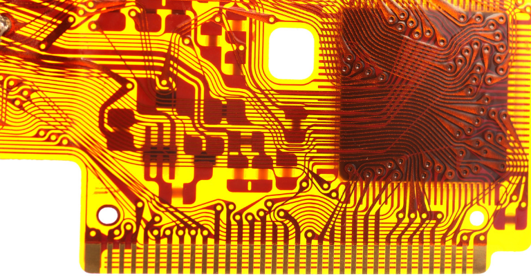
High-speed flexible circuits are alternatives to traditional printed circuit board (PCB) circuits that are chosen for their ability to be malleable during installation or throughout the life of the circuit. Flexible circuits are handy, but the most significant problem they present is poor performance in high-speed applications. For this reason, PCB designs that incorporate this type of technology sometimes have to be creative in the application of flexible circuits.
Electrical Properties of Flexible Circuits
PCB designers are familiar with the coefficient of thermal expansion (CTE) presenting problems in both flexible and non-flexible circuits. Flexible circuits are not usually protected as well as the circuitry that lies within a multi-layered PCB, raising their CTE.
Another issue that affects the electrical properties of flexible circuits is that the substrates they are on tend to absorb moisture causing low thermal conductivity. This also leads to a higher CTE value and poorer overall conductivity. One of the best materials to overcome these problems has been found to be liquid crystalline polymer (LCP). LCP in high-speed PCB applications has also been shown to work best when flex circuits are used with rigid circuits.
Circuit Connections and Electrical Properties
Binding flex and rigid circuits is an art all on its own. For flexible circuits, designers find that binding the circuit to the PCB helps to lower the CTE by reducing the amount of stress on the circuit. Using flexible clads that will allow for minimal movement of the circuit will help to reduce stress as well. Other materials that may be used in conjunction with flexible clads are dielectric films and coverlays or bond plies. These are essentially malleable adhesives that can be applied to different parts of the flexible circuitry to reduce stress and increase the conductivity of the circuit.
Design flaws around flexible circuitry tend to revolve around solder points that are too close to flex points, stack traces that reduce the amount of flexibility, and damage to coverlays or bond plies after processing of the PCB. For example, additional etching steps or copper plating after flex circuits are in place can damage the films used to hold the circuit in place.
Mechanical Properties of Flexible Circuits
As described above, flexible circuits are mechanically constrained primarily by the CTE of the circuit in place. New developments in laminate materials for things like bond plies and other connectors are increasing the mechanical abilities of flexible circuitry. Bond plies and coverlays can reduce the number of physical connections needed to the rigid part of the PCB structure, increasing their mechanical flexibility.
Wrapping Up
Flexible circuits are used in many industries, such as medicine, automotive, and aerospace. 3D printing is beginning to allow for more freedom in creating flexible circuits. For example, 3D printing can allow for the PCB substrates to be layered and printed out right on and of any material of choice. 3D printing will abrogate the need for complex machinery produced to create one PCB build or another. PCBs and films can be dynamically latticed to fit the design rules of future and current applications for flex circuitry. LCP and new materials for bond plies and coverlays will also improve performance for flexible circuits.
If you are ready to start, contact us today for a custom quote tailored to your specific needs.


