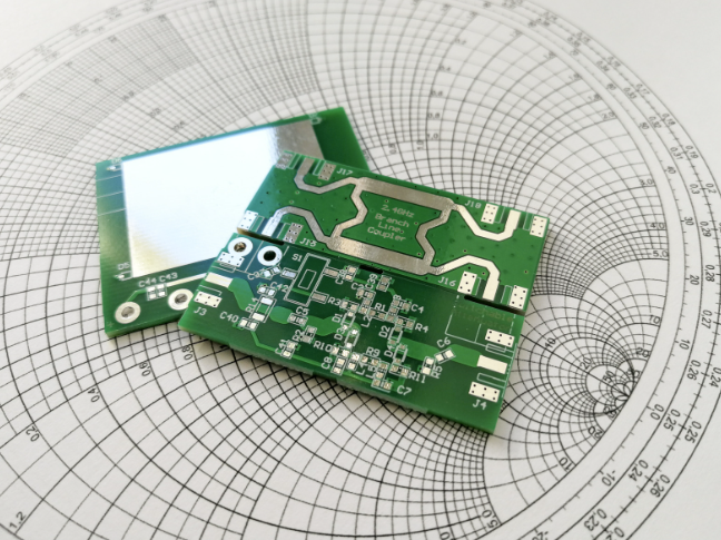
Under extreme performance conditions, specialized materials such as Rogers material are required to produce the best functionality for manufacturing RF PCBs.
Traditional printed circuit boards are produced using materials that are relatively resistant to heat, making them less expensive to produce. But something like a smartphone isn’t intended to join you on a space shuttle, and limited cell reception aside, their PCB isn’t designed to operate in an environment with high temperature fluctuations. Radio frequency printed circuit boards are a far better option.
What factors need to be considered in RF PCB manufacturing, and what makes Rogers material suitable for these applications? In this blog, we unpack everything you need to know about radio frequency printed circuit boards.
A Primer on Radio Frequency Printed Circuit Boards (RF PCB)
Radio Frequency printed circuit boards are circuit boards that operate at higher frequencies than other types of PCBs. By definition, RF PCBs operate within 300 MHz and 3 GHz. They are used for situations that require high speed, such as sensors, wireless controllers, and even robotics.
Due to the special properties of RF PCBs, special materials and manufacturing processes are required during fabrication and assembly. Thus, several variables must be considered with choosing RF PCB materials:
Coefficient of Thermal Expansion (CTE)
To serve their purpose, RF PCBs need to be able to operate in high-temperature applications. The coefficient of thermal expansion is a measurement of how robust a circuit board is under high temperatures. RF PCBs should be made of materials with a low CTE.
When temperatures get high, the materials used in PCB manufacturing can expand. When temperatures exceed 170°C, a PCB reaches its glass transition temperature, where the polymers of epoxy move from hard materials to soft ones. Generally, high temperature PCBs should aim for a continuous thermal load that is 25°C below the glass transition temperature.
Moisture Absorption
Printed circuit boards are sensitive to changes in atmospheric humidity, and RF PCBs are no exception. Considerations around an RF PCB’s moisture absorption should be made around their end-use application. If an RF printed circuit board is exposed to harsh environmental conditions, materials with low moisture absorption should be factored into their manufacturing. Conversely, these properties are less important if they are kept indoors in a moisture-controlled environment.
Spacing, Skin Effect, and Crosstalk
In RF applications, signals can get jumbled and result in malfunctioning. Crosstalk is the phenomenon in which a board begins to interact with itself, and signals will enter the wrong components. Skin effect is when a trace’s resistance rises, and resistive losses occur. Both of these problems can be resolved by minimizing the spacing between trace length and width.
Dielectric Constant (Dk)
The dielectric constant is a material’s ability to store electrical energy in electric fields, depending on its direction with the axis. HF PCBs require stable Dk values over a wide range.
With these variables in mind, material selection is of the utmost importance when designing RF PCBs. This will ensure that you are getting the best reliability and results in high frequency applications.
FR-4 vs. Rogers Material: Which is Best for RF PCBs?
What is FR-4 Material?
Traditionally, printed circuit boards are made of a material called FR-4 (Flame Retardant Level 4). This material is a composite made out of glass fiber and epoxy, and is laminated with copper foil on either or both sides. For normal applications, this material is more than sufficient, and provides an excellent value for its function.
But some printed circuit boards need to function in extreme settings. This could be mobile networking, microwave applications, or even operating in outer space.
Placing FR-4 materials in these settings can lead to malfunctioning due to a variety of reasons, such as the temperature. More, the services they provide are often crucial to high-value projects, such as military use. Put simply, you don’t want a printed circuit board malfunctioning if you are in a space shuttle.
This is why Rogers material is considered ideal for radio frequency printed circuit boards.
What is Rogers Material?
The makeup of Rogers material differs greatly from FR-4 material. Rogers material doesn’t contain glass fiber in the middle, and is primarily ceramic-based. Several variations are available to printed circuit board manufacturers, with different combinations of glass-reinforced and PTFE ceramic laminates.
These elements allow Rogers material several benefits that make it ideal for RF PCB applications, such as:
High Heat Resistance
As mentioned above, when materials are subject to high temperatures, they can expand and even grow soft. Rogers material is designed for ideal thermal management. Thanks to its material makeup, it is less prone to softening and warping. The glass transition temperature of Rogers material approaches 280°C.
Lower Moisture Absorption Rate
Rogers materials have a very low moisture absorption rate compared to traditional PCB materials. This makes Rogers material ideal for unconventional environments, hence its use in aerospace and military applications.
Stable Dielectric Constant
A PCB operating in high frequency applications needs a constant, stable Dk value over a large range. A frequency range greater than 500MHz requires nonstandard materials, limiting the laminates available to designers. Rogers materials perform best in these environments, as they have low dielectric loss and an expansive frequency range. A full list of materials, along with their dielectric constants and frequency ranges can be found here.
Given the benefits afforded by Rogers material, why aren’t they used universally? In short, these specialized materials are more expensive than their FR-4 counterparts. For their price, Rogers materials offer excellent performance and robusticity, making them a popular option for specific industries that require adherence to judicious guidelines.
Applications for Rogers Material and RF PCBs
Radio frequency printed circuit boards are designed for devices that require high reliability and can handle harsh conditions. Some of the most common applications for RF PCBs include:
Aerospace – From airplanes to space shuttles, RF PCBs are depended upon for reliability in extreme circumstances. These printed circuit boards can be found in everything from radars to rockets, and are part of what makes air travel so reliable and safe.
Telecommunications – Our ability to communicate effortlessly across the world through mobile phones and the internet depend largely in part on RF PCBs. Satellites must operate seamlessly in earth’s orbit, where environmental shifts can be at their most extreme.
Military Applications – Keeping the peace requires high-functioning equipment that can operate with pinpoint accuracy. Missile defense systems, drones, and military aircraft all use RF PCBs with zero margin for error.
Consumer Electronics – RF PCBs are even found inside your smart phone! Although they aren’t designed around the same atmospheric shifts you might find outside the stratosphere, they are located in radios, sensors, and even your TV remote.
Whether you’re looking for RF PCBs for smart devices or smart bombs, you need a printed circuit board manufacturer that you can rely on for best-in-class service. That’s where we come in.
Imagineering Inc specializes in creating printed circuit boards that can handle the most rigorous standards. We are AS9100D certified, working alongside key players in aerospace manufacturing as a trusted partner. Every one of our boards meet class 3 standards. In short, we have the resources you need to make your printed circuit board process seamless and cost-effective. Contact us today for more information about our services.


