
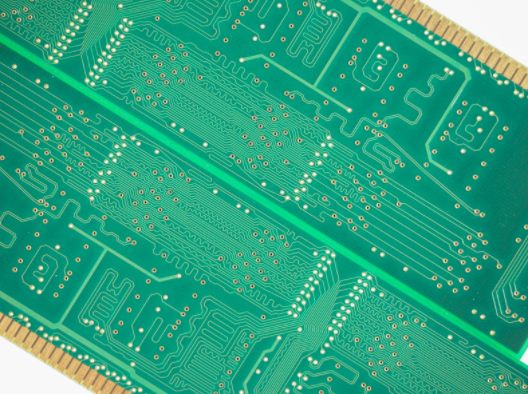
A PCB design can be electrically sound and still run into production delays if the manufacturing package is incomplete. For fabricators and assemblers, a CAD file is more than a design export. It is the instruction set that turns design intent into a reliable, buildable board.
In this guide, we’ll cover:
- What fabricators mean by a CAD file
- What files and details belong in a fabrication package
- What assemblers need beyond the bare-board data
- Common CAD file problems and best practices before manufacturing
To start, it helps to clarify what a fabricator actually means when they ask for a CAD file.
What Does a Fabricator Mean by a CAD File?
In PCB manufacturing, a CAD file is not usually one standalone file. It is the complete set of exported production data a fabricator uses to review, prepare, and build the board. That package translates the designer’s intent into the instructions needed for CAM review, DFM review, fabrication, testing, and, when applicable, assembly.
A schematic or native design file may show how the circuit should function, but it does not give the manufacturer everything needed to produce the physical board. Fabricators typically need outputs such as Gerber X2, ODB++, or IPC-2581 files, along with NC drill files, a netlist, fabrication drawings, stackup details, material notes, copper weights, tolerances, and testing requirements.
In short, the CAD file package should remove guesswork. It tells the manufacturer what to build, how the layers align, where holes go, and which requirements need special attention.
What do Fabricators Need in a CAD File Package?
For fabrication, the CAD file package needs to define the physical board clearly enough for the manufacturer to prepare the job in CAM, verify manufacturability, and build the board without interpreting missing details. A complete package usually includes three categories of information.
Layer and Image Data
The core production files show what each layer of the PCB should contain. Depending on the designer’s tools and the fabricator’s preferred workflow, this may include:
- Gerber X2 files
- ODB++ files
- IPC-2581 files
These files define the copper layers, solder mask, paste layers, silkscreen or legend, board outline, and other image-based features. Gerber X2 adds attributes that help identify layer function, while ODB++ and IPC-2581 can package more manufacturing data together in a more integrated format.
Drill, Route, and Netlist Data
Fabricators also need accurate hole and routing information. NC drill files should identify plated holes, non-plated holes, vias, slots, cutouts, finished hole sizes, and drill tolerances.
When available, an IPC-D-356 netlist or equivalent test data gives the fabricator a reference for checking opens, shorts, and electrical continuity against the intended design.
Stackup and Material Requirements
The CAD file package should also include the details that affect how the board is built, not just what it looks like. Key requirements may include:
- Layer order
- Finished board thickness
- Copper weights
- Dielectric materials
- Controlled impedance requirements
- Special laminate or material notes
Missing or unclear information in these areas can create engineering questions before production begins, especially on multilayer, high-density, RF, or impedance-controlled boards.
What do Assemblers Need Beyond the Fabrication CAD File?
Fabrication files tell the manufacturer how to build the bare board. Assembly files tell the assembler how to place, solder, inspect, and verify the components that turn that board into a working PCBA. That distinction matters because a board can be fabricated correctly and still create assembly problems if the supporting files are incomplete.
Bill of Materials
At minimum, the assembler needs a bill of materials, or BOM, that matches the board revision. The BOM should clearly identify:
- Reference designators
- Quantities
- Manufacturer part numbers
- Approved alternates
- Package or footprint details
- DNP or no-pop components
The goal is to make it clear which parts are required, which may be substituted, and which should not be installed.
Pick-and-Place Data
The assembler also needs centroid or pick-and-place data showing where each component goes on the board. This file should include each component’s X/Y location, rotation, board side, and reference designator.
Assembly Notes and Inspection Requirements
Depending on the project, the assembly package may also need paste layer or stencil data, assembly drawings, polarity markings, test points, programming notes, and inspection requirements.
These details connect directly back to fabrication. Solder mask registration, pad geometry, surface finish, board flatness, and dimensional accuracy all affect how reliably components can be placed and soldered.
Drawings, Notes, and Specifications That Prevent Delays
A complete CAD file package should include more than production data. Fabricators and assemblers also need clear drawings, notes, and specifications that explain how the board should be built, inspected, and delivered. These details help answer the practical manufacturing questions that may not be obvious from Gerbers, ODB++, IPC-2581, or drill files alone.
What Should a Fabrication Drawing Include?
A PCB fabrication drawing should include the board dimensions, outline, tolerances, layer stackup, material, copper weight, surface finish, solder mask color, legend color, IPC class expectations, RoHS or lead-free requirements, testing requirements, and current revision.
Keep Documentation Consistent
Assembly drawings should identify component placement, polarity, orientation, keep-out zones, mechanical constraints, coating areas, and any special soldering or inspection instructions.
Most delays happen when documents conflict. File names, drawings, BOMs, placement data, and revision notes should all point to the same version of the design.
Common CAD File Problems and Best Practices Before Manufacturing
Most CAD file problems happen when the manufacturer has to stop and interpret something that should have been clear in the production package. Missing drill files, unclear layer order, incomplete stackup details, mismatched revisions, and conflicting assembly data can all slow quoting, CAM review, DFM review, fabrication, or assembly.
Before sending a CAD file package to manufacturing, designers should:
- Export all fabrication and assembly files from the same approved revision.
- Use clear file names that identify the project, board revision, and file type.
- Include Gerbers, ODB++, or IPC-2581 data, along with drill files, drawings, BOM, pick-and-place data, and netlist when applicable.
- Confirm that the BOM matches the placement file and assembly drawing.
- Review exported files in an independent viewer before submission.
- Call out controlled impedance, HDI features, special materials, tight tolerances, surface finish, IPC class, and testing requirements.
Clean files do not replace engineering review, but they make that review faster and more useful. The more complete the package is, the easier it is for the manufacturer to identify real manufacturability concerns instead of chasing missing information.
Build Better CAD File Packages With Imagineering
A complete CAD file package gives fabricators and assemblers the information they need to quote accurately, review manufacturability, build the bare board, place components, and verify the finished product. Gerbers, ODB++, IPC-2581 files, drill data, BOMs, placement files, drawings, stackup notes, material requirements, and revision details all play a role in keeping production clear and efficient.
The stronger the package, the fewer assumptions the manufacturer has to make. If you want a PCB partner that can review your files carefully, catch issues early, and help move your design into production with fewer delays, work with Imagineering on your next build.
Quick Summary
This blog explains what fabricators and assemblers actually need when they ask for a PCB CAD file. It covers the files, drawings, notes, and revision details that help manufacturers quote accurately, review manufacturability, build the bare board, assemble components, and avoid preventable production delays.
PCB CAD File Package FAQs
A complete CAD file package may include Gerbers, ODB++, or IPC-2581 files, NC drill files, fabrication drawings, stackup details, BOM, pick-and-place data, and revision notes. The exact package depends on whether the project includes fabrication only or full assembly.
Fabrication drawings clarify requirements that may not be obvious from the exported files, such as tolerances, materials, surface finish, IPC class, and testing requirements. They help prevent back-and-forth during quoting and CAM review.
Designers should export all files from the same approved revision, use clear file names, review outputs in an independent viewer, and make sure drawings, BOMs, drill files, and placement data all match.